
Guide for type selection
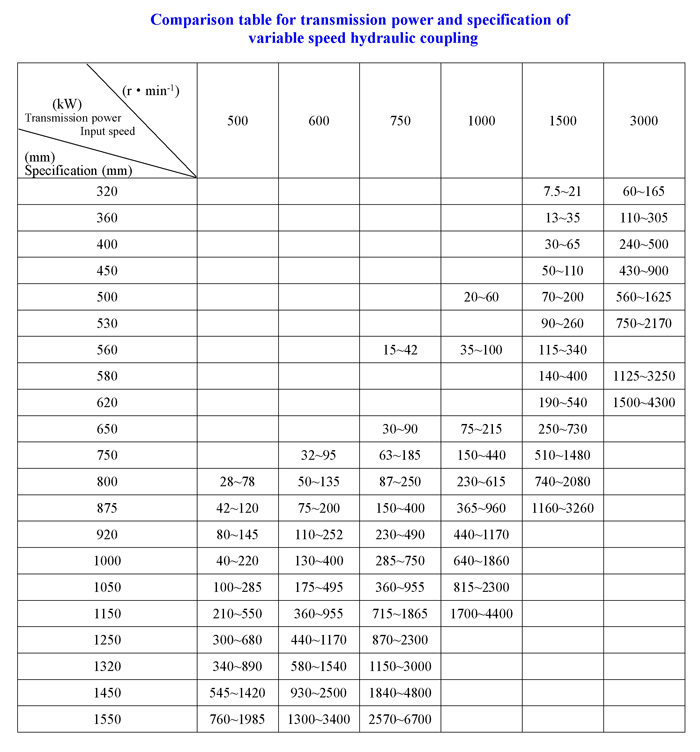
1. According to the rated speed (i.e. the input speed of hydraulic coupling or drive unit) and required transmission power of motor, refer to the power characteristic curve (P-n) and technical parameter schedule in the catalogue to select the model and specification of hydraulic coupling and drive unit;
2. When selecting a drive unit for YOCz acceleration type coupling, first divide the rated speed (nT) of working machine by the hydraulic efficiency (ηy=0.97) of hydraulic coupling to calculate the speed (nB) of pump impeller in the coupling, then divide the shaft power (PT) of working machine by the hydraulic efficiency of hydraulic coupling to calculate the power (PB) of pump impeller in the coupling. Select the required specification in the power characteristic diagram according to the values of PB and nB.
3. The coefficient design must take into account the efficiency loss of hydraulic coupling or drive unit and shaft coupling. When making type selection matching for variable speed coupling, the design margin of the rated power of motor relative to the shaft power of working machine is 1.04~1.06; when making type selection matching for drive unit of coupling, the design margin of the rated power of motor relative to the shaft power of working machine is 1.06~1.08.
4. The rated slip ratio of hydraulic coupling is 1.5~3%, the range of transmission power listed in the technical parameter table is that corresponding to the rated slip ratio in high efficiency area, the selection of coupling with the transmission power beyond the lower limit in the technical parameter table will be favorable to improving the transmission efficiency, but will reduce the cost performance.
5. When the hydraulic coupling and drive unit are used for centrifugal machinery with M∝n2, the range of speed regulation is 1~1/5; when they are used for constant torque machinery with M=C, the range of speed regulation is 1~1/3.
6. The characteristics of speed regulation when the hydraulic coupling is matched with different loads (see the attached characteristic curve diagram).
7. When making type selection, the rotational direction of equipment must be indicated, i.e. when viewing from the end of motor, the input shaft of coupling and drive unit rotates clockwise or counterclockwise.
Operating principle
The hydraulic coupling is equivalent to a combination of centrifugal pump and hydraulic turbine, the hermetic working chamber formed between the pump impeller (centrifugal pump) and turbine (hydraulic turbine) is full of liquid (generally mineral oil). When the prime mover drives the pump impeller to rotate, the pump impeller is just like a centrifugal pump, which makes the liquid in the working chamber flow along the passage on the blade of pump impeller from inner edge towards outer edge and impact the turbine at high speed, thus the mechanical energy input by the prime mover is converted into the kinetic energy and pressure energy of liquid; under the impact of liquid flow, the turbine is started, and meanwhile drives the working machine to rotate, the turbine is just like a hydraulic turbine which converts the kinetic energy and pressure energy of liquid into the output mechanical energy. Then, the liquid flows along the passage on the blade of turbine from outer edge towards inner edge and enters into the pump impeller again, thus beginning the next cycle. Through this kind of repetitive energy conversion, flexible power transmission is realized between the prime mover and working machine.
Speed regulation principle
The speed regulation of variable speed hydraulic coupling is realized through the volume regulation of transmission medium. In the liquid storage chamber formed by the pump impeller, turbine and housing of coupling, there is a scoop tube which can slide radially. When the coupling rotates, due to the action of centrifugal force, a rotating liquid ring is produced in the liquid storage chamber, with certain pressure on the surface of liquid ring, thus making the liquid discharged from the liquid storage chamber through the opening of scoop tube. When the opening of scoop tube is located at the bottom of liquid ring, the liquid in the chamber will be totally discharged, the working machine is under no-load, low-speed or still condition; when the scoop tube is located in the middle part, the working machine operates at medium speed and at medium load; when the scoop tube is located on the inner edge of liquid ring, the working machine operates at full speed and at full load. The coupling can control the scoop tube through an electric actuator or hydraulic oil cylinder to change the thickness of liquid ring arbitrarily, thus changing the volume of the part of transmission medium which can directly tranmit the power, therefore, the coupling can realize stepless speed regulation.